# View Bar
# Copy View

Batch copy and create views for multiple levels.
- Parameter Explanation
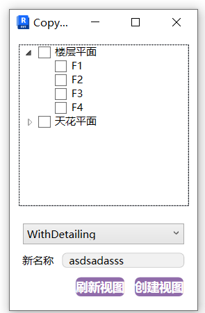
- The window shows the plan views existing in the project.
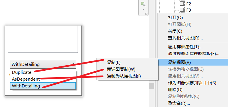
- The options bar below corresponds to the project's built-in copy view options.
- New Name: The name of the copied view plane.
- Usage
Select the view plane to copy, set the copy conditions and name, then click Create View.
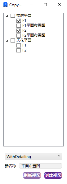
If views are added or deleted in the project, click Refresh Views to update.
Bilibili video demo → Copy View (opens new window)
# View Template
Supports quick application of preset view templates, maintaining view presets through an independent inheritance mechanism, and supporting custom scale and graphic settings to avoid template association locking.
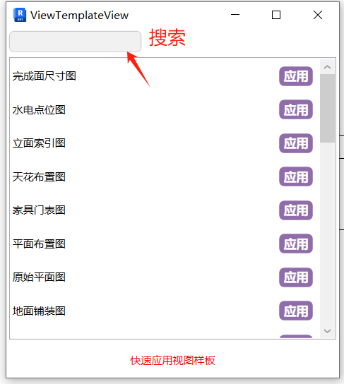
- Steps
Directly select and apply the desired view template in the active viewport.
Bilibili video demo → View Template (opens new window)
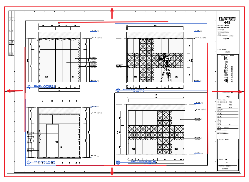
# Create Sheets

Automatically configure viewports and calculate sheet parameters for batch sheet generation.
Viewport layout on sheets is automatically arranged based on viewport size and title block size. It's recommended to adjust viewport scales appropriately according to the sheet first.
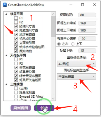
- Parameter Explanation
The following parameters are set once and saved as user data. All values are actual distances on the printed drawing.
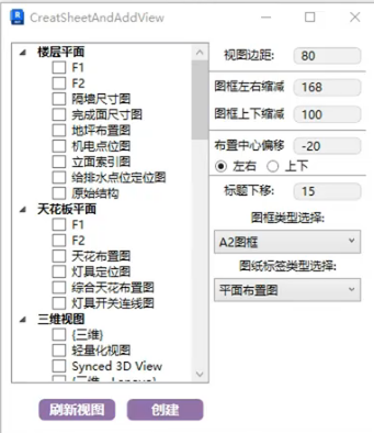
View Margin:
The spacing between view crop boundaries on the sheet.
Sheet Reduction:
The reduction distance between placed views and the four edges of the sheet.
Layout Center Offset:
A composite center point is calculated from all viewports placed on the current sheet. This offsets that composite center point relative to the sheet frame center, horizontally/vertically.
Title Offset:
The offset distance between the view crop boundary and the viewport title.
Title Block Type Selection:
The title block type for the sheets to be generated.
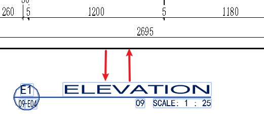
Sheet Label Type Selection:
The viewport title type for views on the sheet.
Select the view planes to layout, adjust the corresponding title block and label types, and click Create.
When creating plan series sheets, each viewport may have a different label. You can select individual labels per sheet, or batch-create with one label and manually replace labels on sheets afterward.
Bilibili video demo → Create Sheets (opens new window)
# Sheet Numbering
Rename and reorder sheet numbers.
- Parameter Explanation
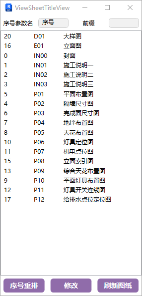
- Sequence Parameter Name: Set this according to the corresponding language version. The currently displayed Chinese preset field can be ignored.
If the sequence parameter name is not visible in the sheet properties panel, manually add the corresponding project parameter to the sheet.
- Sheets can be directly selected and dragged to the desired position.
- Select sheets to renumber. For sheets with the same prefix, enter the desired prefix in the Prefix parameter and modify to get prefix + sequence sheet numbers.
- After adjusting the sheet order, click "Renumber" below to number sheets according to the adjusted order.
Bilibili video demo → Sheet Numbering (opens new window)
# Legend
Ensure a legend view already exists in the project with legend components placed. If not, create one and place any legend component.
Steps: Set scale and row spacing → Click the command.
Bilibili video demo → Legend (opens new window)
# Parts
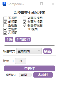
This feature includes single-component part drafting and multi-component part drafting:
For single-component drafting, the view name is the component name, so ensure standard naming.
For multi-component drafting, the view name is set separately.
Multi-component drafting steps: Marquee-select elements to draft → Select a line parallel to the front view as the view reference line.

The annotation style is the section symbol style.
Bilibili video demo → Parts (opens new window)
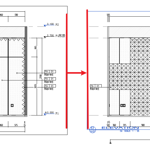
# Elevation/Section 3D Lock

Uniformly adjust the viewport height for generated elevation views.
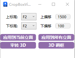
The selected top/bottom levels and offset values uniformly adjust the top and bottom crop box boundaries in the elevation viewport.
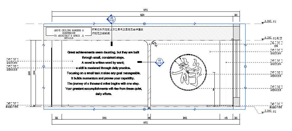
The blue box in the drawing is the adjusted crop box.
When adjusting multi-level elevation views, do not use the "Apply to All Elevations" button. Use "Apply to Current Elevation Only."
Plan to 3D / 3D Frame Adjustment:
Steps: Adjust height range → Click "Plan to 3D" in plan view.
3D Frame Adjustment: Directly adjust the height range of the 3D view.
Bilibili video demo → Plan to 3D / 3D Frame Adjustment (opens new window)
# Free Viewport

Define the view crop box by mouse marquee selection.