# Rooms
# Room Toolbox

Watch tutorial video on Bilibili → Room Parameters, Room Curve Numbering, Room Cleanup, Name Reset, Room Solid, Write Room, Room Finish, Clearance Analysis (opens new window)
# Room Curve Numbering
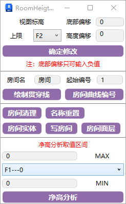
Number rooms in sequence along a passing curve.
Note: The passing line must be a single line — it can be a straight line, curve, spline, etc.
The room name must be correctly filled in — numbering applies to the specified room name.
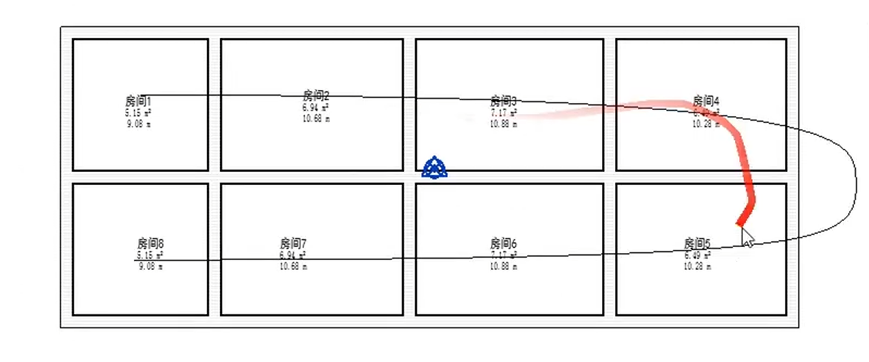
Room numbers are assigned based on the curve's path.
# Room Parameters
Adjust room heights in the current view for room-related calculations.
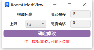
Purpose: Think of a room as an invisible box. To make this box contain all elements in the current room, adjust its bottom and top to enclose the room's components. Default room parameters don't fully cover the entire room space.
The bottom offset is typically set to -50 to include the floor area. The upper limit is usually based on the bottom of the upper floor.
# Room Cleanup
Clean up unplaced rooms and rooms smaller than 1 square meter, including rooms created at different phases. Unreasonable rooms are cleaned up together.
# Name Reset
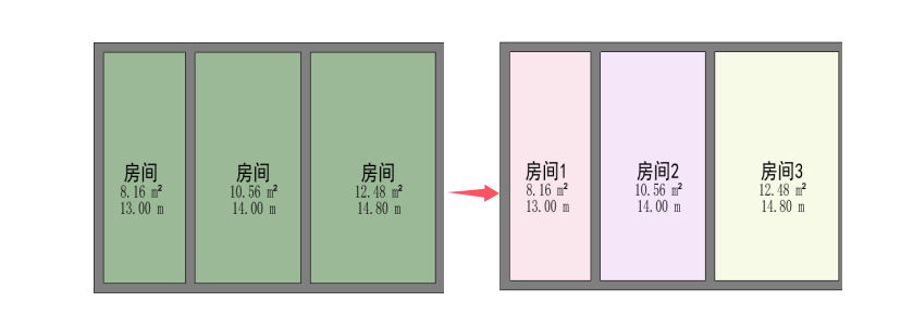
Encode rooms with the same name in the view for more accurate differentiation in schedules.
# Room Solid
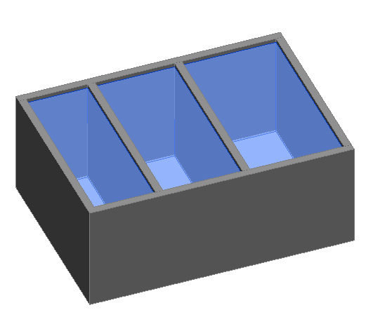
Generate model solids of room spaces for easy viewing of room parameter status and exporting to IFC.
# Write Room
Assign the current room's name parameter to components within the room. This allows scheduling by room zone in schedules.
Before writing rooms, add a "Room" project parameter to components and ensure room parameters have been adjusted.
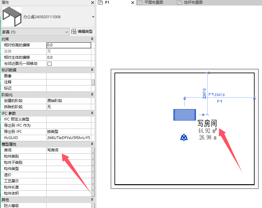
After selecting a room, you can see components within the room space labeled with the room name.
# Room Finish
Pick a room to write wall, ceiling, and floor finish material information.
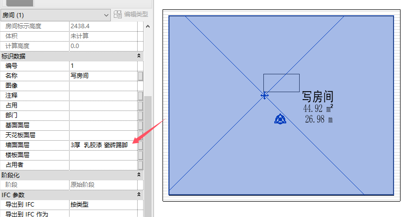
In the example, only wall finishes were created. You can see the corresponding finish types written in the room properties. Multiple types are written in separate lines and visible in schedules.
# Clearance Analysis
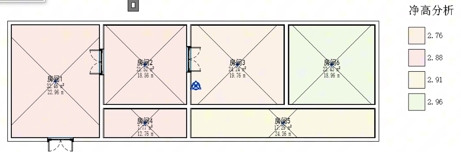
Add room clearance parameters and generate clearance analysis diagrams using color schemes.
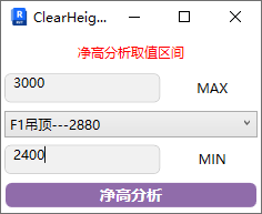
In the parameters, select the ceiling level section, then set max and min values to calculate only the lowest elevation of components within that range.
Combined with color schemes, you can generate the following clearance analysis diagram.